|
This page is intended to explain a proposal about how to manage projection onto
a curved surface, in such a way as to preserve continuity between separatly
projected images.
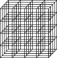
Transforming coordinatesIt seems likely to be desirable to apply an arbitrary transform by dragging around some control points.The idea is to implement the transform by applying a 3D tranform all the points in space before sending them to the OpenGL renderer. It is assumed that the world is being stored using three-dimensional coordinates. The world is divided up into a large number of smaller cubes:

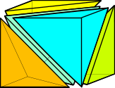
Each cube is then mapped onto a distorted image of itself. The corners of the distorted cubes are stored in a table. A mapping between the regualr cubes and the distorted cubes is applied. The map can be implemented using linear transformations as follows: Start by dividing the cubes into into five tetrahedra:

One vertex of each tetrahedron is chosen to be used as an origin. The three sides leading away from that vertex form the basis of a 3D coordinate system. The coordinates of the point in question within the cube are determined with respect to this coordinate system. It's image is then found by using the corresponding coordinate scheme defined by the corresponding vertex and sides of the distorted tetrahedron.
Creating the transformed coordinatesThe coordinates of the corners of the transformed cube can be created by modelling a lump of elastic material with skewers embedded in it, and joining at a central point. By manipulating the ends of the skewers, the desired transformation can be arrived at, and then the relevant coordinates can be stored for use.This is a likely to be a relatively complex procedure.
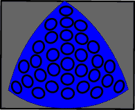
Avoiding distortionIf the projectors are further away from the dome's surface than the radius of the dome, different parts of the dome will be at different angles to the projector. This will cause geometric distortions in any projected shapes.In particular, any circles projected onto any area not perpendicular to the projector will not remain circular. The following diagram indicates the approximate shapes which should be plotted in order for the projected result to appear as correctly-proportioned circles.

Since objects are rendered as texture mapped triangle strips, one possible way of dealing with this is to adjust the four "corners" of each object, in such a way as to compensate for the effect. I believe objects will generally be rendered as "decals" - i.e. they will be fixed perpendicular to the camera - so applying the global tranformation (described above) to the four corners of the object is likely to fail - since the absolute coordinates of the corners are not known. However, I believe a relatively simple "fudged" transformation is likely to be effective under these circumstances.
|